What is the Difference between Earthing, Grounding and Bonding?
There is unusual confusion to understand the basic concept and main difference among grounding, earthing and bonding even some professionals interchanged the word for earthing, grounding and bonding such as earthing bond, bonding ground etc. In addition, electrical bonding is a totally different thing other than grounding and earthing.
To the point, Grounding and Earthing is the same concept expressed by different terms used for them. There is a small difference between earthing and grounding which we will discuss in detail as follows.
- The term Grounding is the same as used for Earthing in the USA and Canada based on NEC, CEC, IEEE, UL & ANSI standards.
- The term Earthing is used in EU, UK and other countries who follow IEC and IS standards.
- The term bonding or electrical bonding is same used in US, UK & EU (NEC & IEC) for connecting and jointing two conductors (wires, pumps, machines, pipes etc) and metallic bodies (non-current carrying during the normal operation) permanently to equalize the potential difference on both machines or systems connected by bond wire.
In short, the grounding and earthing are the local version terms used in the US and UK. For example, protective ground “PG” is used in the US while protective earth “PE” is used in the UK and EC. Similarly, Ground Potential Rise “GPR” or Earth Potential Rise “EPR” are used in the US and UK respectively. In other simple words, the terms “two way switch” and “three way switch” are used for the same thing used for the same purposes in the US and UK respectively.
What is Grounding?
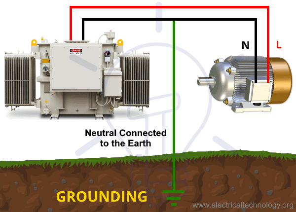
Grounding is the connection between live parts of a machine (which carries current in normal operation) and earth such as the neutral of a generator or neutral point of a star connected power transformer. This grounding provides an effective path to the fault currents from the equipment to the power source which leads to protect the power system installations and devices.
Grounding is also used to balance the unbalance system. For example, all three phase (lines) become unbalanced when a fault occurs in the system hence, the grounding discharge the faulty current to the earth and make the system balanced once again having the total neutral current as “0” (it is not possible to gain this value in specific cases but it reduces to the almost ideal case i.e. nearest value).
Moreover, grounding provides protection against the surge voltage (lightning, line faults and surges) and discharges the over-voltage to the ground which makes the system stable and reliable with maximum transformer efficiency.
- Both AC and DC circuits in electrical and electronics engineering need a “0V” as reference potential known as ground which makes possible the flow of current from the generated source to the load side.
- It is not mandatory to always connect the ground to the earth such as in vehicles and automobiles where the ground is connected to the metallic body and chassis which is further insulated from the earth through rubber tires. The ground is earthed at consumer end or power distribution point in a power distribution system.
- It is not necessary to ground the neutral wire as there may exist a neutral to ground voltage due to the voltage drop in the electrical wiring or these two wires used in other systems.
Good to Know:
- Grounding can be used as a Neutral, but Neutral can’t be used as a ground. For this reason, never ever ground the neutral wire twice (i.e. Neutral should be grounded (earthed) at the end of the consumer unit or distribution transformer in the power house or utility poles.
- More than one ground will create problems for proper operations of the OCPD (overcurrent protection devices) as the amount of current will not be sufficient to operate those protection devices. In some cases, the ungrounded WYE circuits (protective grounding of the equipment is still connected) are used to prevent the operation of OCPDs (single phase to ground fault).
- The GFCI (ground-fault circuit interrupter) is a protective device used to detect the current imbalances between the Hot (ungrounded) and Neutral (Grounded) conductors and trip the circuit in case of fault to protect the lives (These protective devices are not recommended in the hospital ICUs and other sensitive areas needing the continuous and uninterruptible power supply. Learn more about GFCI & AFCI Wiring installations.
What is Earthing?
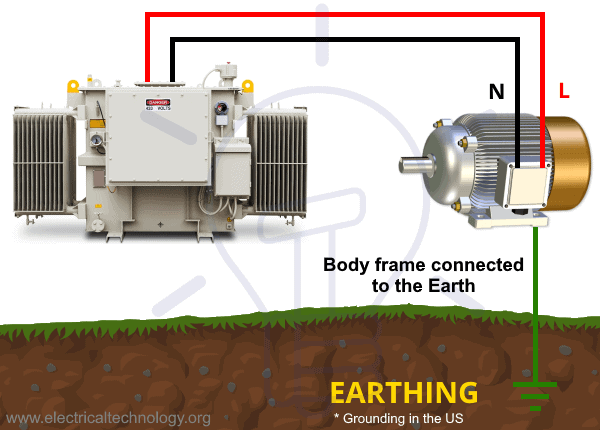
Earthing is the connection between the metallic (conductive) parts (such as body frame, metallic enclosure which in non current carrying during normal operation) of an electric appliance or installation and earth (ground). Electrical Earthing is also known as Grounding in the US.
If the live (phase, hot or line) wire touches to the metallic body frame of a machine or panel box enclosure and someone comes in contact (by touching) the machine frame or metallic enclosure, he will get a tough electric shock (due to the high positional between ground and the body frame) even electrocution may occurs due to the fault current flowing through the victim body to the earth.
For this reason, a bare or green or green with yellow stripe wire is connected between the metallic body and earth electrodes (or earth plate buried in the ground) through the earth continuity conductor. This way, the fault current discharges to the ground, hence the earthing system protects the personal from the hazardous electric shock.
It is recommended both earthing (grounding in the US) and bonding between the external surfaces and metallic parts of the machines and ground for additional and perfect protection. Moreover, high voltages machines such as motors, transformers and generators should be earthed (grounded) twice i.e. from two different and separate locations (using separate earth conductors and earth electrode plates).
Earthing also provides a safe discharge path for lighting strokes through gap, surge and lightning arresters, hence makes the system reliable with smooth operation.
What is Bonding?
Bonding or electrical bonding is the process of connecting and permanently joining two electrical conductors, machines, pipes, devices and all the metallic parts in the power installations. In this process, all the dead metallic parts (non-current carrying under normal condition) of the installations are connected through a conductor wire which equalize the intentional difference between them.
This way, a person is still protected (from getting electric shock) even if he touches the two (bonded) machines at the same time connected to the different sources. In other words, the bonding rod equalizes and makes sure the same electrical potential levels on the both surfaces. This way, there is no chance of current flow due to the lack of potential difference, hence the system and personnel is well protected.
For the reason mentioned above, a well bonding system connected to the earth is used to protect the persons, devices, equipment and other installations as the earthed bonding system makes sure all the connected devices are the same level of voltage, hence no chance for discharge & current flow.
Bonding to electrical earth is used extensively to ensure that all conductors (person, surface and product) are at the same electrical potential. When all conductors are at the same potential no discharge can occur.
Bonding ensures that these two things which are bonded will be at the same electrical potential. That means we would not get electricity building up in one equipment or between two different equipment. No current flow can take place between two bonded bodies because they have the same potential.
If a single machine or panel box is properly earthed (grounded) and bonded to another box, there will be no chances of current flow due to the zero (grounded) potential between the bonded boxes or machines.
Bonding itself won’t protect, but provides the low impedance return path to the power source. This way, a high amount of current will start to flow which leads to trip the protective circuit breaker and eliminate the fault.
Bonding is necessary due to the following two safety related reasons..
- If there is no bonding, a person touching two different equipment at the same time (both equipment having different levels of voltages) will act as equalizer and get electric shock due to the energy buildup between potential differences at both ends.
- If a live wire touches the metallic body of the machine and comes in contact with a person (who is working on it) may get hazardous, even fatal electric shock.
The properly bonded as well as grounded (earthed) system provide protection against both the above mentioned scenarios.

Main Difference Between Grounding and Earthing
Both grounding and earthing are almost the same thing i.e. connecting an electrical device to the ground (earth plate or earth electrode though continuity coadjutor or protective rod). This system provides a must have reference voltage in the circuit, to protect the installations for lightning strikes, and discharge the fault current to the earth hence the system protects the lives.
For non US residents, there is a small (almost negligible) difference between the ground and earth as follows.
- Two terms are used for the same thing i.e. Grounding is used in the USA (NEC) and Earthing is used in the UK (IEC) same as three way switch (in the US) while two way switch (in the UK) while both are used for same purposes.
- Grounding is a single low impedance path to discharge the faulty current to the ground while ground is a double path (sometimes a return path for main current and source for unwanted currents).
- When a neutral of the three phase unbalanced connection connects to the earth (to balance the system), it is known as “Grounding”. On the other hand, “Earthing” is the connection between the devices / installations and earth to protect against damages of devices and equipment and reduce the risk of electric shock.
- Ground is the common point in the circuit to maintain the voltage levels and balance the unbalanced phases while earthing protects the system against high voltage surges.
- Ground as a neutral earth is used for installation systems and equipment protection while Earthing provides protection against electric shock and used (to save human/animal lives) as a safety measure.
Comparison Between Earthing, Grounding and Bonding
The following table shows the comparison and differences between bonding, earthing and grounding.
| Characteristics | Grounding | Earthing | Bonding |
| Terminology | Grounding is the commonly word used for earthing in the North American (US) & Canadian standards like,NEC, CEC, IEEE, ANSI and UL. | Earthing is used in European, Common wealth countries and Britain (UK) standards like IS and IEC etc while Grounding is a little bit different. | The electrical bonding is the same term used in both NEC & IEC (US & UK) but totally different than grounding and earthing. |
| Symbol |  |  |  |
| Definition | To connect the current carrying part of the electrical system to the earth electrode buried in the ground through earth continuity conductor. | To connect the metallic (conductive) parts (such as body, frame which in non current carrying during normal operation) of an electric appliance or installation to the earth (ground) is called Earthing (and / or Grounding in the US). | To connect two electrical systems (such as wires, equipment and pipes etc) together to bring them at the same potential level while they are non-current carrying during the normal operation. |
| Location of Installation | Connection between the current carrying parts of the system (such as Neutral as a return path for current) to the ground. | Connection between the metallic body frame and earth plate in the ground through earth continuity conductor & earthing lead. | Connection between two equipment, wires, pipes etc (which are non-current carrying during normal operation through a conductor. |
| Types | Solid grounding, resistance grounding and reactance grounding. | Pipe earthing, plate earthing, water main earthing, Rod earthing & stripe wire earthing. | Main bonding and supplementary bonding. |
| Wire Color Code | Green with Yellow stripe or Bare Conductor. | Green or Green with Yellow stripe or Bare conductor. | Green with Yellow stripe. |
| Path | Provides a return path to the current in case of abnormal and fault conditions. | Provides a path to a large surface to zero volt potential. | Provides a path to equalize the potential difference on two difference surceases. |
| “0” Potential | Neutral connected to ground may have some potential (zero potential where the algebraic current is zero known as “Virtual Grounding”.) | Zero Potential due to the physical connection between equipment and ground. | Same and zero electrical potential on both connected devices. |
| Protection | It protects the electrical systems and power equipment during the fault condition as it provides a return path for the phase currents. | It protects a person from hazardous electric shock as it is a preventive measure to discharge the unwanted electrical energy to the ground. | It protects equipment and personnel by reducing the current flow between two machines having different potential. the Bonding itself does not protect anything without earthing |
| Examples | Neutral point of a star connected transformer or current carrying part as neutral in the generator connected to the ground. | The metallic body frame and enclosure of the electrical machines (transformer, motors, and generators etc) connected to the earth electrode (earth plate). | Any conductor wire connected between two metallic bodies of the electrical machines & devices to equalize the potential difference on them. |
| Usage | It is used to balance the unbalanced load and protect the system. | It is used to provide protection against both electric shock and faults in the system. | It is used to trip the circuit breaker when high current flows due to existence/change in the positional difference. |
| Applications | Grounding provides an effective return path to the current between electrical equipment and power system. | Earthing draws the unwanted energy to the ground to protect the person who touches the metallic body of the machine during faults. | Bonding ensures both the connected devices at the same level of voltage and provides a low impedance path back to the source to trip the CB in case of fault currents. |


